
NETWORKING
Data Center Networking Explained
A technician-friendly view of how servers, switches, VLANs, routing, addressing, optics, redundancy, and network services work together inside a data center.
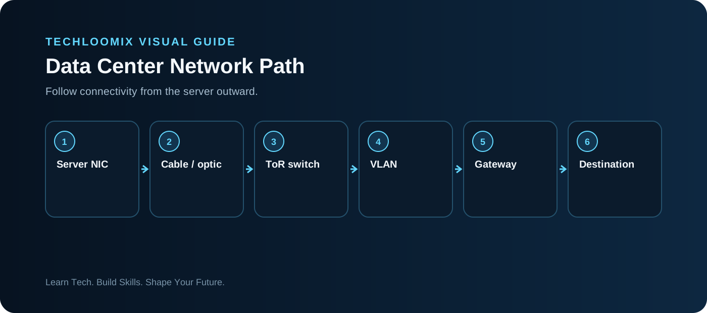
SIMPLIFIED PACKET PATH
Start at Layer 1
Servers connect through copper or fiber. Before touching configuration, verify power, cable/optic type, seating, port identity, link state, cleanliness where appropriate, and the expected physical path.
Layer 2 switching
Ethernet switches learn MAC addresses and forward frames. VLANs create separate logical Layer-2 domains on shared switching infrastructure. Access and trunk configuration determine how VLAN traffic reaches endpoints and other switches.
Layer 3 routing
IP addresses and prefixes determine whether a destination is local. Traffic for another subnet is normally sent to a default gateway, where Layer-3 routing determines the next path.
Network services
DNS helps applications find services by name. DHCP can provide addressing information. NTP keeps time aligned. Authentication, load balancing, firewalls and monitoring may also sit in the path.
Redundancy changes troubleshooting
Data centers often have multiple links, switches or paths. A service may remain partially available even when one component fails, so topology and monitoring context matter.
Troubleshoot progressively
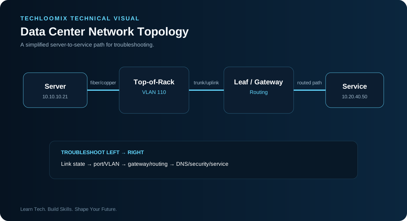
Do not jump from “cannot connect” to replacing hardware. Establish scope, then check physical state, link, local configuration, VLAN, gateway/routing, DNS/security policy and finally application behavior.
HANDS-ON LAB
Hands-on lab: build and break a two-VLAN network
- Create two VLANs in a simulator.
- Place two endpoints in the first VLAN and one in the second.
- Verify same-VLAN communication.
- Configure or simulate inter-VLAN routing.
- Break one access VLAN assignment and observe the symptom.
- Restore it and document the evidence that identified the fault.
TROUBLESHOOTING WORKFLOW
NEXT STEP
Practice. Document. Explain.
Reading creates familiarity. Hands-on work plus clear documentation creates evidence of skill.